RLH-A

There is a trend in complete drive trains, just as in the entire automotive construction branch, towards minimizing the objects in motion. At the same time, the functional complexity is increasing and costs are being reduced. As a result, increasingly complex components are being used in the motors and gears. These highly stressed components require a combination of hardness and toughness – a combination which is very difficult to achieve with traditional hardening processes. Thus Scansonic has developed a hardening optical system that can be specially adapted for a variety of hardening tasks.

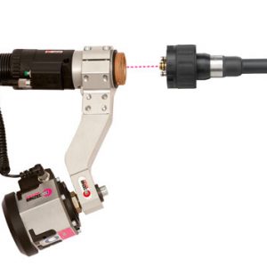
RLH-A in the scapacs-optic buildig blocks is a 1-D scanner with integrated highly dynamic temperature control. This system enables the components described above to be hardened in a selective and controlled process.

  • Allows the hardening of complex and variable components in power-train and hardening applications.
  • Variably adjustable process parameters: track mid-point; track width left and right; pre-heating and hardening temperatures and power; defocussing; and emissions coefficient. Parameters can also be changed during the process.
  • Reliable hardening and quality: made possible by the highly dynamic temperature control mechanism via the variable scanner mirror speed and subsidiary slow laser power controls (based on Patent EP 08 022 027 B2).
  • Significantly reduced set-up time; process can be easily adapted and adjusted; the optional auto-focus module allows spot diameter to vary without requiring a change to the operating clearance.
  • By using scapacs® components, the optical system can be optimally adapted to the laser source and the process parameters (fibre diameter, laser source, required power distribution).
  • Optionally, a monitoring camera can be integrated into the system.
  • Optionally available with external line projector so that operating clearance can be optimally set.

Variable fibre coupling

  • Trumpf-D
  • Trumpf-B
  • Optoskand QBH
  • Optoskand MMI

Collimation

  • Fixed collimation or with integrated auto-focus module.
  • The auto-focus module allows the focus diameter to be modified based on the process. The stand-off clearance to the component does not need to be adjusted.
  • An additional safety glass under the end of the glass fibre prevents contaminants from penetrating while the fibre is being changed.

Pyrometer

  • Integrated camera-based pyrometer.
  • The path of the pyrometer measurement beam is coaxial with the path of the laser beam.
  • Thus the scanner also moves the pyrometer’s measurement field.
  • The measurement distance from the pyrometer to the laser focus is constant which allows it to be optimally adjusted.
  • An error in the scanner positioning does not affect the measurement result.
  • Temperature fields can be selected using software functions. No mechanical adjustment of the sensors is required.

Monitoring camera

  • Integrated coaxial-aligned monitoring camera; camera observation is independent of the position of the scanner mirror.
  • Thus the component remains still for the observer (this is not the case for the pyrometer camera).
  • The location of the hardening track can be checked easily and securely using the camera.
  • So the initial commissioning process is faster and less prone to errors.

Scanner unit

  • Highly dynamic scanner unit.
  • 1-D linear projection.
  • Variable programming options for the scanned line  (wide left, right and centre position).
  • External cooling for the entire optics and the scanner unit. This prevents the penetration of cooling water into the optical system.

Flange mounting on the robot

  • Can be quickly swapped out with high-precision tool coupling.
  • Measurement for the optics, just as for all scapacs® devices, is enabled at the appropriate measuring stations.

Safety glass drawer

  • Dust-proof drawer for safety glass.
  • Additional protective glass between the lens and the safety glass drawer: offers extra protection for the focusing lens.
  • Efficient cross-jet module (not shown here).
  • Process jet uses nozzle from Silvent (not shown here) in order to prevent water vapour from the quenching bath from reaching the optics.

Controller

  • Modern, bus-based control strategy.
  • Actuators and sensors are bus nodes.
  • The RLH controller is the bus master and is separated from the RLH processing head.
  • Controller can be installed as needed (for example, in the facility’s equipment cabinet).
  • The RLH system can communicate with the production facility on different Fieldbus types, such as Interbus, Profibus, Devicenet or Profinet.
  • A facility PC can be used for parameterization.


Power supply±24V / max. 10A
Weightapprox. 15 kg
Limiting acceleration (mechanical), in/not in operating mode3 g / 5 g
Protection classBased on IP64 (when plugged into fibre)
Cooling water quantity1,4 l/min at 6 bar (estimated)
Type of cooling waterSuitable for DI water (stainless steel version), conductivity to 2 μS/cm
Ambient temperature rangeStorage: -25 °C to 70 °C, cooling water drained; during operations: 10 °C to 45 °C, non-condensing
Power supply24 V
Video signalBAS
Fieldbus typesSelection of: Profibus, Interbus, Profinet, Devicenet. Number of assigned words: 6. Parameterization using facility PC, communication with RLH controller via TCP/IP
Operating wave length1000 to 1080 nm, thin-disc laser to fibre laser
Fibre couplingSelection of: Trumpf B and D, and Optoskand models QBH and MMI
Permissible laser powermax. 6 kW
Total divergence angle/angle of acceptance250 mrad (99 % power capacity)
Beam parameter product, laser power unitbetter/equal 25 mm mrad
Track width, max. in TCP50 mm (in the regular system; extensions possible)
  • Wire feed drive (DFE)
  • Media coupling (MEKO)
  • Media coupling general application interface MEKO-GAS (HTK box)
  • Crash Sensor
  • Pressure wheel (ADR)
  • Pointer with adjustable focal point
  • Cross-hair generator (FKGA)
  • Wire cutter 45° DAS
Download Brochure