RLW-A

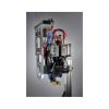
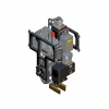
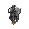
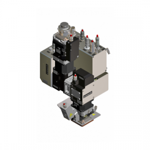
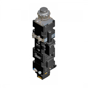
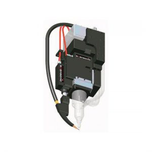
The RLW-A sets new standards in contactless fillet welding and enables overlap joints to be replaced by fillet welds. This reduces joint flanges and requires less laser energy for the same seam cross-section. The processing optics ensure precision, dynamics and reproducibility along with cost-effective operation.

Function description

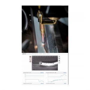
The RLW-A system combines optical seam tracking with scanner axes. During the robot movement, the system measures the joint and controls the highly dynamic scanner levels online. Measuring precision is ensured by the patented coaxial guidance of laser beam and measurement light in the same optical system. The position of the laser spot remains precisely on the joint. This makes remote fillet welding possible on 3D body-in-white components.

Areas of application

  • Laser welding
  • Fillet welds e.g. on attached assemblies (doors, decklids, etc.), A and B pillars, front/rear bumpers, door sills, roof, and vehicle underbody
  • Fillet welds on T and lap joints, open edges
  • Adjustable offset defines overlap seams to the abutting edge

Advantages

  • Fillet welds enable reduction of flange lengths in vehicle construction
  • Lower weight reduces fuel consumption and CO2 emissions
  • Large working distance allows overrunning of clamps and fastening fixtures in the process, significant reduction in cycle time compared to tactile systems
  • Application-specific scan fields for significant reduction in consumption costs
  • Simplified operating concept with all laser process parameters set via the RLW-A GUI and controlled/regulated by the RLW-A controller
  • Spot size is adjusted via autofocus and kept constant during the process using the seam-tracking values

Properties

  • Robust seam tracking Nahtführung
  • Easy parameterization of seam tracking through separate parameteriziation software (GUI)
  • Plug & Play processing system – an autonomous system with a simple robotics communication – no complex sensor-robot interface is require
  • No relearning of path programming necessary – based on standard welding optics
  • Scanners with highy dynamic adjustment reaction up to 1000Hz
  • Modular construction provided by Scansonic‘s scapacs® modular system: interface with practically any optical units, fiber couplings, Fieldbus interfaces, etc

Supported Laser

  • Fibre laser
  • Disk laser

Features

  • Fiber couplings for the following types of fiber optic cables: Trumpf-B,Trumpf-D, Optoskand QBH
  • Fieldbus types: Profibus, Interbus, Profinet, Devicenet, Ethernet/IP
  • Interface laser power: Current and voltage interface

Options

  • Scan field to choose (small and medium)
  • 2-D modulation scanner system
  • SCEYE observation camera and process logging
  • Velve terminal for cross-jets and cone jets
  • Gap bridging
  • On-the-fly seam tracking
  • Pre-integration of PLASMO pso-sensors
  • Integration of OCT Sensorik from Lessmüller possible
Power supply extern/intern400 V – 6A / ± 24 V – max. 55A
WeightApprox. 25 kg (depending on configuration)
Wavelength1030 … 1080 nm (Disc laser to fibre laser)
Laser powermax. 8 kW
Total angle of acceptance Φ; BPPΦ = 250 mrad (99% power capacity); BPP ≤ 25 mm∙mrad
Optical ratio1:2.9
Scanning field of operationsX = ± 32 mm / Y = ±16,5 mm / Z = ± 10 mm
Focal distanceApprox. 280mm at focal length of f = 500 mm
Positional accuracy with seam trackingX = 0,1 mm / Y = 0,1 mm / Z = 0,5 mm
IP protection degree64
Laser protection class4
Download Brochure